
close
Choose Your Site
Global
Social Media

Views: 0 Author: Site Editor Publish Time: 2025-09-10 Origin: Site


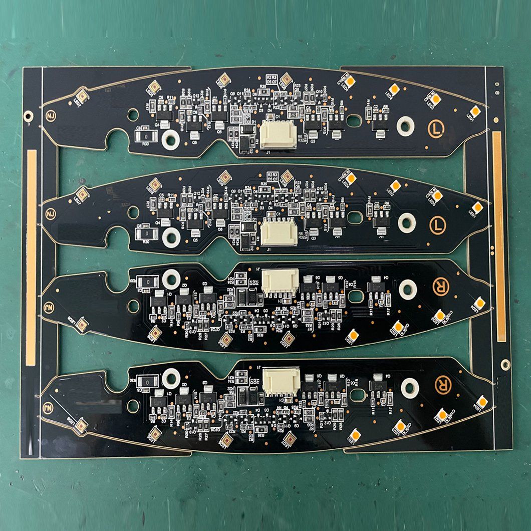
The LED PCB module for automotive lighting is a core component of the automotive lighting system. Its development must consider core dimensions such as optical performance, thermal management, electrical stability, mechanical reliability, and automotive-grade certification. The following are the key technical points for each module:
I. PCB Substrate Selection and Structural Design
Substrate Material Selection
Automotive LEDs have high power density, so high thermal conductivity insulating substrates are preferred:
Metal-based PCB (MCPCB): The mainstream solution is aluminum-based PCB, with a thermal conductivity generally ≥1.5 W/(m・K). For high-power modules (such as headlights and daytime running lights), copper-based PCBs (thermal conductivity ≥380 W/(m・K)) or ceramic-based PCBs (alumina/aluminum nitride, with even higher thermal conductivity but higher cost) are recommended.
Automotive-grade temperature resistance requirements must be met: long-term operating temperature -40℃~125℃, and resistance to thermal shock (-40℃→125℃ cyclic testing).
Insulation Requirements: Use high-voltage, high-thermal-conductivity insulating adhesive with a breakdown voltage ≥20kV/mm to avoid the risk of high-voltage breakdown.
PCB Structure Design
Circuit Layout: Current loops should be as short and wide as possible to reduce line impedance and heat generation. For high-power LED circuits, a copper thickness ≥2oz (70μm) is recommended.
Strong/Weak Current Separation: Automotive lighting modules often integrate driver circuits. LED power lines and driver control lines must be laid out separately with a spacing ≥3mm to avoid electromagnetic interference.
Pad Design: LED pad dimensions must match the LED chip package (e.g., SMD 3535/5050). Thermal pads should be provided to enhance the heat dissipation path of the LED chips.
Pad surface treatment should use ENIG (chemical nickel-gold plating) or OSP (organic solder mask) to meet automotive-grade corrosion resistance and soldering reliability.
Shape and Mounting Holes: The mounting structure should match the vehicle headlight housing. Mounting holes need to be countersunk/beveled to avoid stress concentration; the module edges should have rounded corners to prevent scratches during assembly.
II. LED Device Selection and Optical Matching
LED Chip Selection:
Prioritize automotive-grade LEDs: Must meet AEC-Q102 certification, support wide operating temperature, vibration resistance, and moisture resistance.
Selection by Function:
High/Low Beam: High power (1~5W/chip), high lumen density (≥150lm/W), color temperature around 5500K (meets white light illumination standards).
Daylight Running Lights/Turn Signals: Low power (0.2~1W/chip), daytime running light color temperature ≥6000K, turn signals must meet amber (around 590nm) light color requirements.
Packaging Type: Prioritize ceramic-packaged LEDs, as they offer better heat dissipation and reliability than plastic-packaged LEDs.
Optical Matching Design
LED Chip Arrangement: Based on light distribution requirements (such as regulation GB 4599-2007 "Automotive Filament Bulbs for Headlights"), determine the spacing and angle of the LED array to ensure uniform light spot and no glare.
Optical Lens Matching: The PCB module must reserve lens mounting points to ensure precise alignment between the LED light-emitting center and the lens focal point, avoiding luminous efficiency loss.
III. Thermal Management Design (Core Key)
The light decay and lifespan of automotive LEDs directly depend on heat dissipation. Thermal management must be implemented throughout the entire PCB module development process:
Heat Dissipation Path Design
Establish an efficient heat dissipation path: "LED chip → solder pad → PCB substrate → heat sink bracket → headlight housing".
The aluminum-based PCB and the heat sink bracket must be filled with thermally conductive silicone/thermal pads (thermal conductivity ≥3W/(m・K)) to eliminate contact gaps and reduce thermal resistance.
Thermal Simulation Verification
Using ANSYS Icepak and Flotherm software for thermal simulation, ensure the LED junction temperature (Tj) is ≤120℃ (the rated junction temperature of automotive-grade LEDs is generally 150℃, with a safety margin).
Simulation should simulate extreme operating conditions: such as turning on the lights after prolonged exposure to high summer temperatures or continuous operation.
Heat Reduction Auxiliary Design
High-power modules can have heat sinks designed on the back of the PCB (must match the housing) to increase the heat dissipation area.
Avoid dense localized heat generation on the PCB; rationally distribute the LED layout to reduce heat concentration.
IV. Electrical and Driver Compatibility Design
Electrical Parameter Matching
Input Voltage: Matches automotive power systems (12V passenger cars / 24V commercial vehicles), with a ±20% voltage fluctuation margin (e.g., 12V systems are compatible with 9~16V).
Overcurrent/Overvoltage Protection: The PCB module must integrate a fuse/resetting fuse, or be linked with the driver circuit to achieve overcurrent and short-circuit protection.
Electromagnetic Compatibility (EMC) Design
Automotive lights are automotive electronic components and must meet the requirements of GB 21437-2015 "Electromagnetic Compatibility Requirements and Test Methods for Passenger Cars".
PCB Design Measures:
Add grounding copper foil to cover blank areas of the PCB to reduce electromagnetic radiation.
Add filter capacitors (e.g., 0.1μF ceramic capacitor + 10μF electrolytic capacitor) near the LED in the drive circuit to suppress power supply ripple.
Impedance matching (e.g., 50Ω) for high-frequency signal lines to reduce signal reflection.
V. Mechanical Reliability and Environmental Adaptability Design
Vibration Resistance Design
High-frequency vibrations occur during vehicle operation. The PCB module must meet vibration testing standards (e.g., IEC 60068-2-6):
Select a more rigid substrate (e.g., copper-based PCB) to avoid PCB bending and deformation.
Use rubber gaskets between mounting holes and fasteners to buffer vibration impacts.
Environmental Corrosion Resistant Design
Condensation may occur inside the headlights; therefore, the PCB requires a three-proof coating (moisture-proof, mildew-proof, and salt spray-proof) with a coating thickness ≥20μm, covering the circuitry and pads to prevent oxidation and corrosion.
Automotive-grade waterproof connectors (e.g., IP67 rating) are used, and the connection to the PCB employs a double-fixing method of soldering and potting.
VI. Automotive Certification and Testing Verification
Core Certification Standards
Product Level: Must pass E-Mark certification (EU), DOT certification (USA), and CCC certification (China).
Component Level: The PCB substrate must meet the IATF 16949 automotive industry quality management system requirements, and LED devices must pass AEC-Q102 certification.
Key Test Items
Test Type | Core Item | Test Standard
Reliability Testing | Thermal shock, high and low temperature aging, vibration testing | IEC 60068
Optical Testing | Luminous flux, color temperature, light distribution curve | GB 4599
Electrical Testing | Withstand voltage test, insulation resistance, EMC test | GB 21437
Environmental Testing | Salt spray test, waterproof and dustproof test | IEC 60529
VII. Production Process Control
SMT Process Requirements
The reflow soldering temperature profile must match the temperature resistance characteristics of the LED and PCB substrate to avoid high-temperature damage to the device.
High-temperature lead-free solder paste (melting point ≥217℃) is selected to meet automotive-grade soldering reliability.
Inspection Process
100% AOI (Automated Optical Inspection) is performed to check for defects such as cold solder joints and short circuits.
Sampling is performed for X-ray inspection to verify the solder joint quality of BGA packaged LEDs.


